
RFID Modules - Adding UHF RFID reader capabilities
UHF RFID or RAIN RFID is an emerging IoT technology that is enabling automated workflows for inventory management, asset tracking and authentication solutions across broad markets including retail, logistics, supply chain, healthcare, airline baggage and manufacturing. This broad adoption is driving the need for a variety of dedicated readers, generally fixed and handheld readers, but also embedding reader capabilities into existing devices and appliances. Appliances like refrigerators, smart cabinets, drones, safes, printers, vending machines, ticketing machines and beverage dispensers are all examples of devices that OEMs are looking to add RFID reader capability to make them smarter.
Developers have 3 options when embedding an RFID reader:
- Discrete design – very high engineering investment, generally high cost, best performance
- Chip based design – high engineering investment, lower cost, good performance
- Module based design – low engineering investment (easy), moderate cost, good performance
Most OEMs choose module-based designs to enable fast time-to-market and avoid significant engineering investments before testing their market. OEMs generally plan future products based on reader chips or a discrete design to either lower costs, optimize performance or add custom features.
Key factors to consider when embedding UHF RFID reader capability- Performance
- Read range – tag read distance
- Read rate – tag reads per second
- Power consumption – critical for battery operated devices
- Interfaces
- Electrical
- Software
- Thermal considerations
- Form factor
- Regulatory support
Read range is a key performance metric that typically drives design decisions. Receive sensitivity, transmit power, reader antenna gain and tag performance are the key parameters that determine read range. A simple link budget analysis is shown below to illustrate how an RFID system works. This is a first order free space analysis and does not include common environmental and electrical factors such as polarization loss, shadowing, multipath fading, metal/liquid in the environment or external interface. An RF sight survey and field testing are typically done before validating link margin.
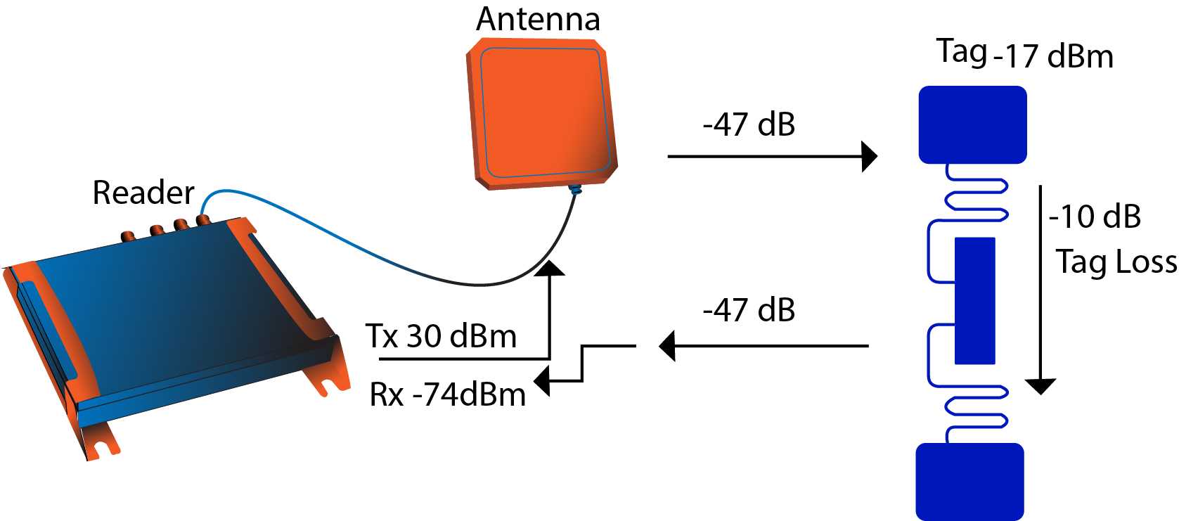
Transmit output power = 30dBm
Antenna gain = 0dBi
Free space pathloss = -47dB (~6meters)
Tag sensitivity = -17dBm (tags typically range from 0dBm to -22dBm)
Receive sensitivity needed: 30dbm -47dB -10dB – 47dB = -74dBm
Transmit output power and antenna gain are the easiest and most common parameter adjustments when designing a system. Reader modules are generally offered in high and low power options: 23dBm for short range and 30dBm for long range; 30dBm (1watt) is typically the maximum conducted output power due to regulatory restrictions; the R4320C offers an additional 1.5dB (31.5dBm) to help compensate for antenna switching and cable losses to the antenna for high performance applications.
Tag read rates can vary due to data rate configurations allowed by the Gen2 ISO 18000-6C protocol or duty cycling to conserve power consumption. The protocol can be configured from 40kbps to 640kbps (dozens to hundreds of tags per second); generally, higher data rates equate to less link margin (tag read range) because both tag and reader sensitivities can degrade 1-3dB from low to high data rates. Reader OEMs typically offer 2-4 modes of operation that can meet the needs of most applications.
Power consumption is usually dominated by the output power; higher output = higher power consumption. This is primarily due to the transmit power amplifier efficiency. Developers use low duty cycling at high data rates to reach desired consumption levels.
Interfaces are an important consideration with any system design. Most modules on the market offer a 5V supply and 3.3V logic over a serial interface (SPI or UART). RF antenna ports typically use SMA or UFL connectors. Lithium Ion battery users tend to add advance power regulation schemes to operate below 3.7V supply to extend operating time as batteries droop.
Software interfaces vary from modern APIs (C, C++, Java, .Net, Android) to simple instruction sets; this is driven by application where embedded systems can vary from basic 8bit micros running state machines to advanced android systems with CPUs. Most module OEMs will offer both interfaces to accommodate broad usage, but it should be noted that simple instruction sets will likely have limited performance.
Thermal considerations are important for device reliability and lead to important design considerations. Full power readers (31.5dBm) operating at full duty cycle can dissipate up to 8watts which requires a considerable amount of heatsinking. Short range and low read rate applications generally do not require heatsinking due to low duty cycling and low output power.
Form factor is usually constrained by the antenna. UHF RFID operates around 900MHz and high gain antennas (~6dBi) tend to be at least 10” x 10”. Many embedded applications do not require high read range and opt for a smaller patch or dipole antenna that can be fairly small (~2” x 1”). As shown by the link budget analysis above, antenna gain can be compensated by TX output power and RX sensitivity.
Regulatory requirements differ depending on region. USA, Europe, Japan and China all have different regulations due to slight frequency differences around 900MHz, different channel schemes and interface / co-existence rules. Most modules can provide global coverage with 2 separate product SKUs.
Questions?
Contact RFID4UStore @ info@rfid4u.com or (877) 599-5584
Recent Posts
-

Top Mistakes Companies Make When Choosing RFID Tags/Labels
Radio Frequency Identification (RFID) technology has become increasingly prevalent across various …Apr 19th 2024 -

What's the difference between Direct Thermal and Thermal Transfer RFID Labels?
In industries such as logistics, retail, and healthcare, RFID (Radio Frequency Identification) techn …Mar 20th 2024 -

Use Cases Where TagMatiks Rugged Tags can be used
What if a machine, construction tool, or cargo container has a standard RFID tag affixed to its e …Mar 19th 2024